Rubber Roll Calculator
Quick Start
A rubber roller against a steel one in a laminator squishes to give you a contact width for a small time, gives you a high pressure, deforms the roller, maybe necessitating a crown. All these effects are calculated for you.
Credits
This is taken from the old AbbottApps which are based on inputs from web-handling experts Dr David Roisum, Dr Dilwyn Jones and Tim Walker.
Rubber Roll Calculator
//One universal basic required here to get things going once loaded
window.onload = function () {
    //restoreDefaultValues(); //Un-comment this if you want to start with defaults
    Main();
};

//Main() is hard wired as THE place to start calculating when inputs change
//It does no calculations itself, it merely sets them up, sends off variables, gets results and, if necessary, plots them.
function Main() {
    //Save settings every time you calculate, so they're always ready on a reload
    saveSettings();

    //Send all the inputs as a structured object
    //If you need to convert to, say, SI units, do it here!
    const inputs = {//Convert them later
        NL: sliders.SlideNL.value,
        Shore: sliders.SlideShoreA.value,
        ROD: sliders.SlideROD.value,
        Rmm: sliders.SlideRmm.value,
        SOD: sliders.SlideSOD.value,
        SID: sliders.SlideSID.value,
        Width:sliders.SlideWidth.value,
        mpm: sliders.Slidempm.value,
    };

    //Send inputs off to CalcIt where the names are instantly available
    //Get all the resonses as an object, result
    const result = CalcIt(inputs);

    document.getElementById('Contact').value = result.Contact;
    document.getElementById('Indent').value = result.Indent;
    document.getElementById('MaxP').value = result.MaxP;
    document.getElementById('Time').value = result.Time;
    document.getElementById('DI').value = result.DI;
    document.getElementById('Crown').value = result.Crown;
    if (result.plots) {
        for (let i = 0; i < result.plots.length; i++) {
            plotIt(result.plots[i], result.canvas[i]);
        }
    }

    //You might have some other stuff to do here, but for most apps that's it for Main!
}

//Here's the app calculation
//The inputs are just the names provided - their order in the curly brackets is unimportant!
//By convention the input values are provided with the correct units within Main
function CalcIt({ NL,Shore,ROD,Rmm,SOD, SID, Width, mpm}) {
    const WebWidth=Width/1000
    const NipLoad=NL*1000/WebWidth
    const RubRad=ROD/2000 //Diam to Radius
    const RThick=Rmm/1000
    const ORad=SOD/2000
    const IRad=SID/2000
    if (IRad>=ORad) IRad=0
    const RRad=RubRad*ORad/(RubRad+ORad)
    const MI=0.25*Math.PI*(Math.pow(ORad,4)-Math.pow(IRad,4))
    const Modulus=21.132*Math.exp(0.0564*Shore)*6895 //Convert to psi then 6895 to Pa
    const Poisson=0.46
    const Crown=2*5*NipLoad*Math.pow(WebWidth,4)/( 210000000000*384*MI)*1000000
    const PFac=(1-Poisson)*(1-Poisson)/(1-2*Poisson)/(1-Poisson*Poisson)
    const CW=Math.pow(3*NipLoad*RThick*RRad/(PFac*Modulus),0.3333) //This is the Half Contact
    const Contact=2000*CW
    const MPS=mpm/60
    const Time=2000*CW/MPS
    const Indent=CW*CW/(2*RRad)*1000
    const MaxP = 0.5 * 1.277 * NipLoad / CW / 1000000.0 //To MPa
    const DI=Crown/Indent/1000


    //Now we return everything - text boxes, plot and the name of the canvas, which is 'canvas' for a single plot
    return {
        Contact:Contact.toFixed(2),
        Indent:Indent.toFixed(2),
        MaxP:MaxP.toFixed(3),
        Time:Time.toFixed(3),
        DI:DI.toFixed(3),
        Crown:Crown.toFixed(0),
    };
}
What are we trying to do?
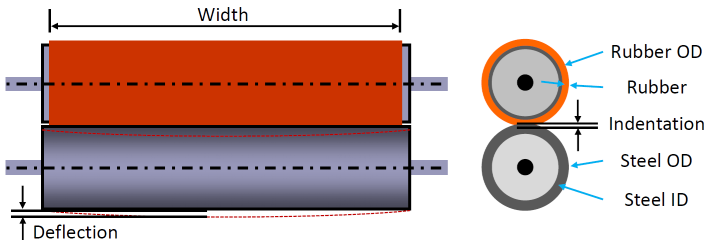 To find out what the effects of Rubber Hardness, Thickness, NipLoad, Roller Diameters/Widths and overall Web Speed might have on your rubber nip, calculating the Contact Width, the Depth of impression, Maximum Pressure, Contact Time and the potential need for a Crowned roller. Nip Mechanics is covered in Chapter 7 of The Web Handling Handbook by Roisum, Walker and Jones. The image, kindly (and expertly) supplied by Tim Walker at WebHandling.com shows the system.
Rubber Footprint
The higher the pressure, the softer the rubber, the thicker the rubber and the higher the roller diameter, the bigger the impression Contact width of the nip. The Indent by which the rubber is deformed follows the same pattern except for the fact that the depth is decreased with larger rollers. The same applies to the maximum pressure (MaxP) within the nip.
The effects of changing variables can seem surprisingly small.This is because the contact width scales as the 1/3 power of load, rubber modulus and rubber thickness. However, a change in Shore Hardness can have a big effect as the relationship of Shore to Modulus is highly non-linear.
Accuracy
The calculated values cannot possibly be accurate. This is mostly because of uncertainties about the rubber itself. The elastic modulus that is used in the calculations is in turn calculated from the Shore Hardness via an industry-standard approximation. Even if this were entirely accurate, rubbers don't behave like perfect elastic materials and once the rubber is moving at speed extra shear and thermal effects come in to play. These effects could have been included in the calculator but in general the only thing that gets measured is the static footprint which, implicitly, is what is calculated here. And even if the rubber calculations were correct, most of us don't know what load we are applying. Generally there is a pressure gauge in the system and we set it at a known pressure which, via various means, gets applied to the roller.
Constant Load v Constant Gap
There is a myth that there is a difference between a Constant Load and a Constant Gap setup. In physics terms there is no difference. A load gives a (negative) gap and a (negative) gap (Depth in the language of RRC) gives a load. Indeed, one way to calibrate the load provided by your Constant Load system is to measure the footprint at a given load, measure the depth of compression of the rubber (i.e. the negative gap) and use the RRC to play with Load values till the Depth/Contact values come out satisfactorily (tweaking the value of Shore along the way to get the effective modulus right).
Of course there is a practical difference in terms of how best to control the system and some prefer Constant Pressure and others prefer Constant Gap. What is important is to know what your Contact/Depth/PMax are for any given settings then use your favoured control system to ensure that your web gets the required treatment when passing through the nip, and that that treatment is in control as other parameters vary in your process.
Integrated Pressure
Your nip is supposed to give some combination of pressure and time in order to do what it has to do. The Time output is therefore a useful indication of whether the combination of nip load, rubber and speed will give be able to achieve the required goals. Doubling the speed is easy, so to keep the same time within the nip "all" that is required is to double the Contact. But as discussed above, the Contact depends on the NipLoad to the 1/3 power, so to double the Contact requires the NipLoad to be increased by a factor of 8. If this is impossible then some combination of increased pressure (a factor of 2.5?), reduced Shore Hardness (60 down to 40?) and increase of the roller diameters (50% more?) can give the required time. These are all approximations, of course, but far superior to mere guesswork.
To Crown or Not to Crown?
Everyone agrees that a bad crown (e.g. a linear profile with a sharp point in the middle!) is worse than no crown. After that, opinions diverge strongly. What is not in dispute is that the load applied to the steel roller will cause it to deform and the size of that deformation can be estimated readily via standard engineering. The Crown figure comes from the combined effect of the NipLoad applied evenly across the roller, the OD and ID of the steel roller, the standard modulus for steel and standard calculations via "moments of inertia". This figure is a good starting point for discussion. If the calculated crown is small then it is certainly not worth the time/expense of creating a crowned roller to compensate - the errors in the manufacture of the crowned roller will be larger than the crown itself. But hold on a moment. Suppose you have to double the line speed and want to keep the same integrated pressure. If this means increasing the NipLoad by a factor of 8 then the crown itself increases by a factor of 8 (these physics are linear) - so for high-speed running a crown might be necessary. That's why we have calculators - to allow you and the team to easily play around with ideas. The alternative to crowning is to have a thicker steel shell (i.e. smaller ID for a given OD) or to go to a narrower width - roller deflection goes as Width^3 for a given constant load.
Please note that for simplicity the rubber roller is assumed to be non-deformable. The rubber roller diameter is used only for calculations involving nip pressure and footprint. It has been argued (rightly) that more often than not the rubber roller is the one more easily deflected. Just enter the values for the most deflectable roller into the "steel" roller values and the diameter of the other roller into the "rubber" OD.
The Walker Deflection-Indentation Ratio
It is always ideal to have the minimum deflection or to create a crowned roller if your deflection is too large. But sometimes it's not possible for reasons of cost or practicality. Web-handling expert Tim Walker (who provided the diagram above) has shown that a thicker rubber covering may allow you to have an acceptable nip pressure profile if the deflection of the roller (calculated as the crown) is well-absorbed by indentation in the rubber. If Deflection/Indentation is < 0.2 then nip load and pressure variations will be below 20% and may be good enough for all but the fussiest of laminations. In addition, Tim says that a D values in the 0.05-0.15mm range are generally OK, implying I values in the 0.25-0.75mm range.